
ゴミ収集車コンパクターの内部:構造、主要部品、作業ロジック
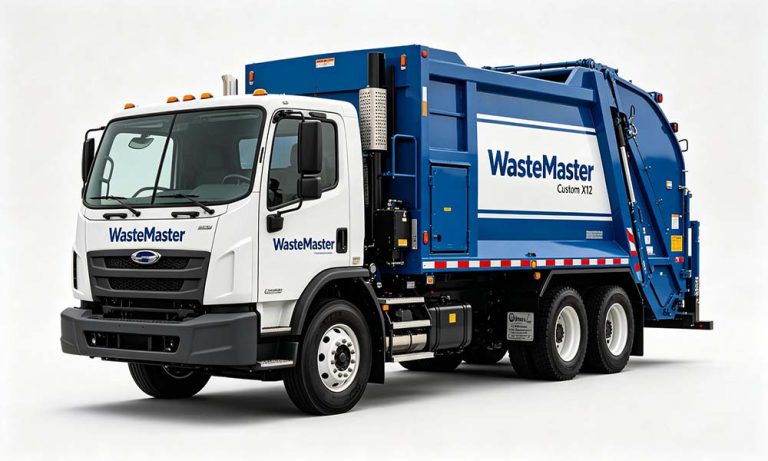
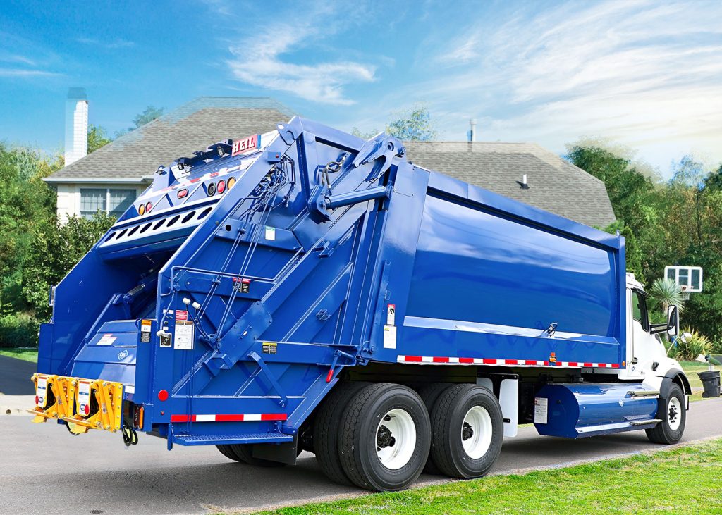
Understanding what happens ゴミ収集車のコンパクター内 helps buyers evaluate performance, durability, and long-term operating cost. A compactor may look simple from the outside, but its internal structure is a combination of reinforced steel, hydraulic force, and synchronized movement. Here, Tops Vehicle breaks down the key components found in modern rear loader and truck-mounted compaction systems.
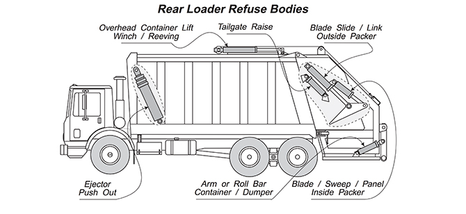
Main Structure of a Garbage Truck Compactor
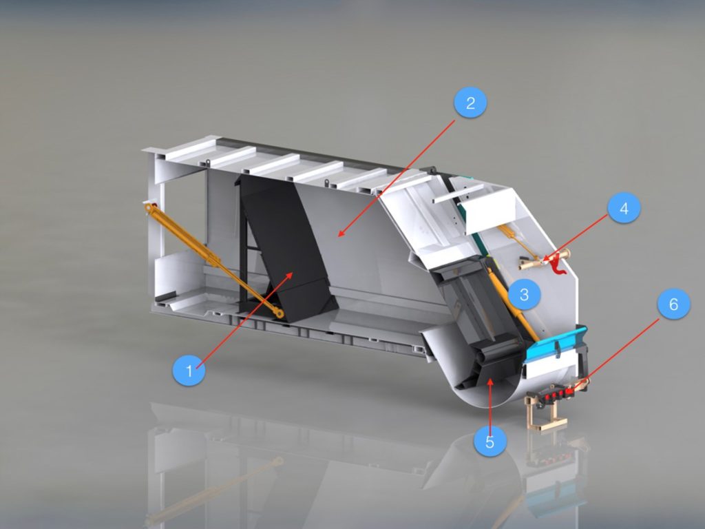
A garbage truck compactor includes three major sections: the hopper, compaction panel system, and the body chamber. Each section works together to compress waste, move it into the body, and keep the loading cycle smooth and safe for operators.
1. Hopper and Loading Section
Hopper Design
The hopper is where waste enters the system. Its internal walls use abrasion-resistant steel to withstand impact from mixed municipal waste, construction debris, and dense organic material. Rear loader compactors often feature deeper hoppers for higher capacity during peak collection hours.
Lifter and Bin-Grabbing Mechanisms
Many export models include European-style bin lifters, fixed arm lifters, or comb-lift designs. These devices reduce manual handling and allow precise, consistent loading.
2. Compaction Plate and Sliding Rail System
Compaction Panel
Inside a garbage truck compactor, the compaction plate is the heart of the system. This reinforced steel plate pushes waste from the hopper into the main body chamber. It operates on heavy-duty sliding rails designed to resist bending and friction over long-term use.
Guide Rails
These rails ensure stable forward and backward movement. High-strength materials and proper lubrication greatly influence service life and compaction efficiency.
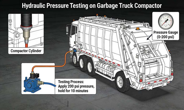
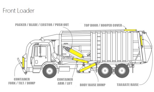
3. Hydraulic Cylinders and Pressure System
Hydraulic cylinders provide the force required for waste compression. The pressure typically ranges from 16 to 20 MPa, depending on the model. Consistent hydraulic pressure ensures that bulky waste is compacted evenly and prevents the compaction plate from twisting under load.
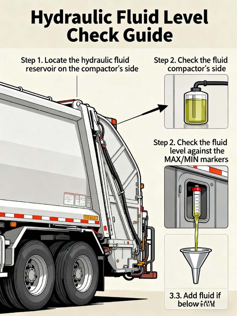
Pressure Relief and Safety Control
To avoid overload damage, modern systems include pressure-relief valves, oil cooling components, and safety interlocks that prevent the compactor from operating when the tailgate is not fully closed.
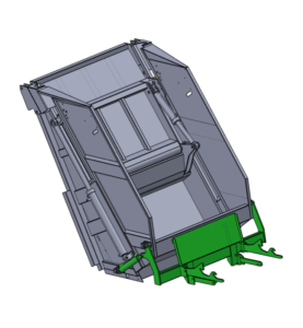
4. Body Chamber and Waste Storage
Reinforced Body Structure
Once compacted, waste enters the body chamber. This area uses stronger steel layers or optional manganese steel for markets that process construction waste or heavy organic refuse.
Smooth Interior Walls
The smooth body interior prevents waste from sticking and supports faster unloading at landfill sites.
5. Tailgate Mechanism and Sealing System
The tailgate includes locking cylinders, sealing strips, and hinge structures that maintain pressure during compaction. A well-designed tailgate prevents leakage and keeps the vehicle safe during travel.
Hydraulic Locking System
This system ensures that no movement occurs during transit, even when the compactor chamber is full.
Why Understanding the Internal Structure Matters
Knowing what is inside a garbage truck compactor helps buyers compare models, evaluate maintenance requirements, and ensure compatibility with local waste management systems. Tops Vehicle provides detailed structural drawings and material customization to match city waste types, bin standards, and road conditions.